
Burn-In Chambers.
Controlled thermal stress environments for screening components, subassemblies, inverters and systems before latent defects become field failures.
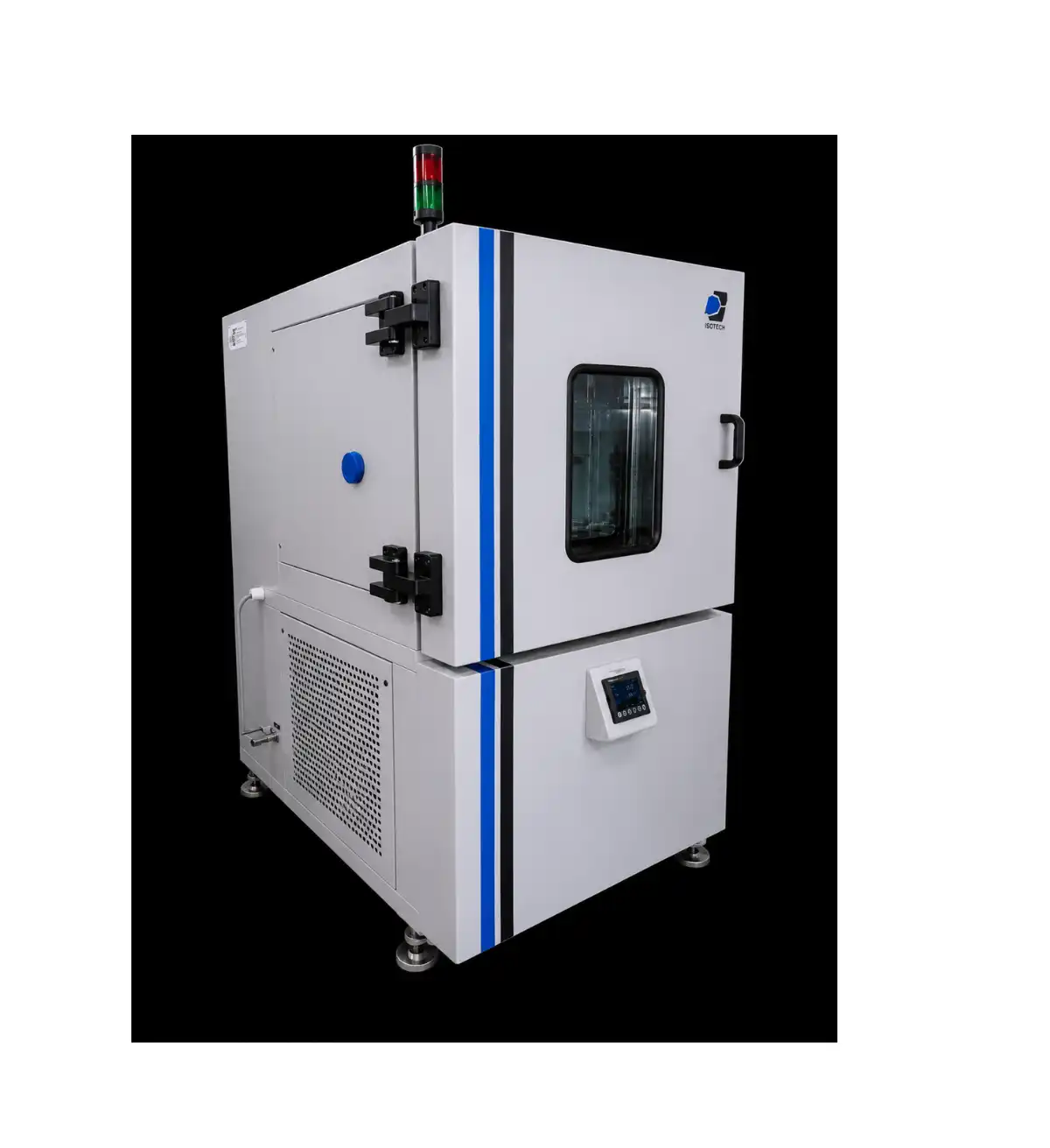
Find the weakness in the chamber—not in the field.
A Burn-In Chamber subjects electronic components and systems to controlled stress over a defined period so latent manufacturing, process or assembly defects can be identified before deployment.
The current ISOTECH material focuses on inverter reliability. It describes visual and physical inspection plus component-level assessment for capacitors, resistors and integrated circuits before assembly, followed by accelerated environmental testing.
Component inspection
Capacitors, resistors and integrated circuits assessed before assembly.
Latent-defect screening
Controlled stress helps surface defects that may otherwise create later failures.
Design-margin discovery
HALT is used to uncover weaknesses at assembly and system level.
Wear-out investigation
ALT supports dominant failure-mechanism and lifetime evaluation.
Production assurance
Burn-in procedures follow robust design and accelerated qualification work.
Increase stress until the design margin becomes visible.
HALT progressively applies environmental stresses to expose design weaknesses, while corrective action builds acceptable temperature, vibration and combined-stress margins.
Cold step
Progressive low-temperature stressing.
Hot step
Progressive high-temperature stressing.
Rapid transition
Temperature change between extremes.
Vibration step
Mechanical-stress margin exploration.
Combined environment
Multiple stresses with maximum loading.
Temperature margin
Understand operating headroom and corrective actions.
Vibration margin
Identify mechanical weaknesses and design limits.
Combined margin
Evaluate interactions that single-stress testing may miss.
Use the right acceleration strategy for the question.
Switch between the published reliability methods to understand their role in design, lifetime and production screening.
Highly Accelerated Life Testing
HALT is intended to uncover design and design-margin issues. Progressively higher stress levels and combinations of temperature and vibration can produce findings within days, supporting corrective action at assembly and system level.
Explore limits rather than simulate normal use.
Plus combined environments and loading.
Accelerated Life Testing
ALT is used to investigate wear-out mechanisms or lifetime within defined confidence limits. Environmental acceleration can shorten the evaluation from normal field periods to weeks or months and help identify dominant failure mechanisms.
Supports prescribed lifetime confidence work.
Along with the controlled test environment.
Production Burn-In Screening
Once a design is capable of the expected lifetime, burn-in procedures are developed to screen for process and assembly defects in production units before those products reach service.
Production-oriented screening after design qualification.
Configured around the product and its risk profile.
System and Subsystem Testing
System-level ALT may integrate multiple units, such as an inverter and power supply, inside a large controlled facility. Subsystems can be tested in smaller environmental enclosures or integrated within unit- or system-level equipment.
Integration within a controlled facility.
Selection follows size, load and test objective.
From design risk to production assurance.
The published Burn-In material outlines a staged reliability approach rather than a single isolated chamber cycle.
Identify potential causes
Verification begins from design failure-mode and effects analysis.
Check critical components
Visual, physical and application-specific inspection before assembly.
Expose design weakness
Use progressive stresses to identify temperature, vibration and combined margins.
Improve the design
Implement corrective actions until acceptable margins are achieved.
Investigate lifetime
Study acceleration, wear-out mechanisms and qualification confidence.
Test the performance envelope
Evaluate operation at environmental and resource extremes.
Screen production units
Identify process and assembly defects before deployment.
Use evidence to release
Assess test data against the approved reliability plan.
Accelerate the environment around a powered system.
The current ISOTECH material presents photovoltaic grid inverters as the primary application. It connects environmental stress, duty cycle, solar-resource extremes and powered operation with lifetime and production-quality objectives.
Temperature acceleration
The published material identifies the Arrhenius model as a common temperature acceleration basis for ALT.
Duty-cycle acceleration
PV-grid-inverter tests may run continually rather than follow the sun-cycle limits of field exposure.
Power and temperature cycling
Published inverter methods include temperature, temperature-humidity voltage, temperature cycling and power cycling.
Solar simulation context
Solar-simulation methods can reproduce cycling associated with environmental and solar-resource extremes.
Envelope performance
Testing at environmental extremes informs qualification and insight into wear-out lifetime.
Two temperature ranges. Large configurable test spaces.
The current ISOTECH page publishes two logic-programmable Burn-In Chamber models. Exact volume, loading, ramp rate, uniformity, electrical feed-throughs and powered-DUT provisions must be selected around the application.
Cabinet and large-system configurations.
Published product views associated with component, inverter, subassembly and system-level reliability programmes.
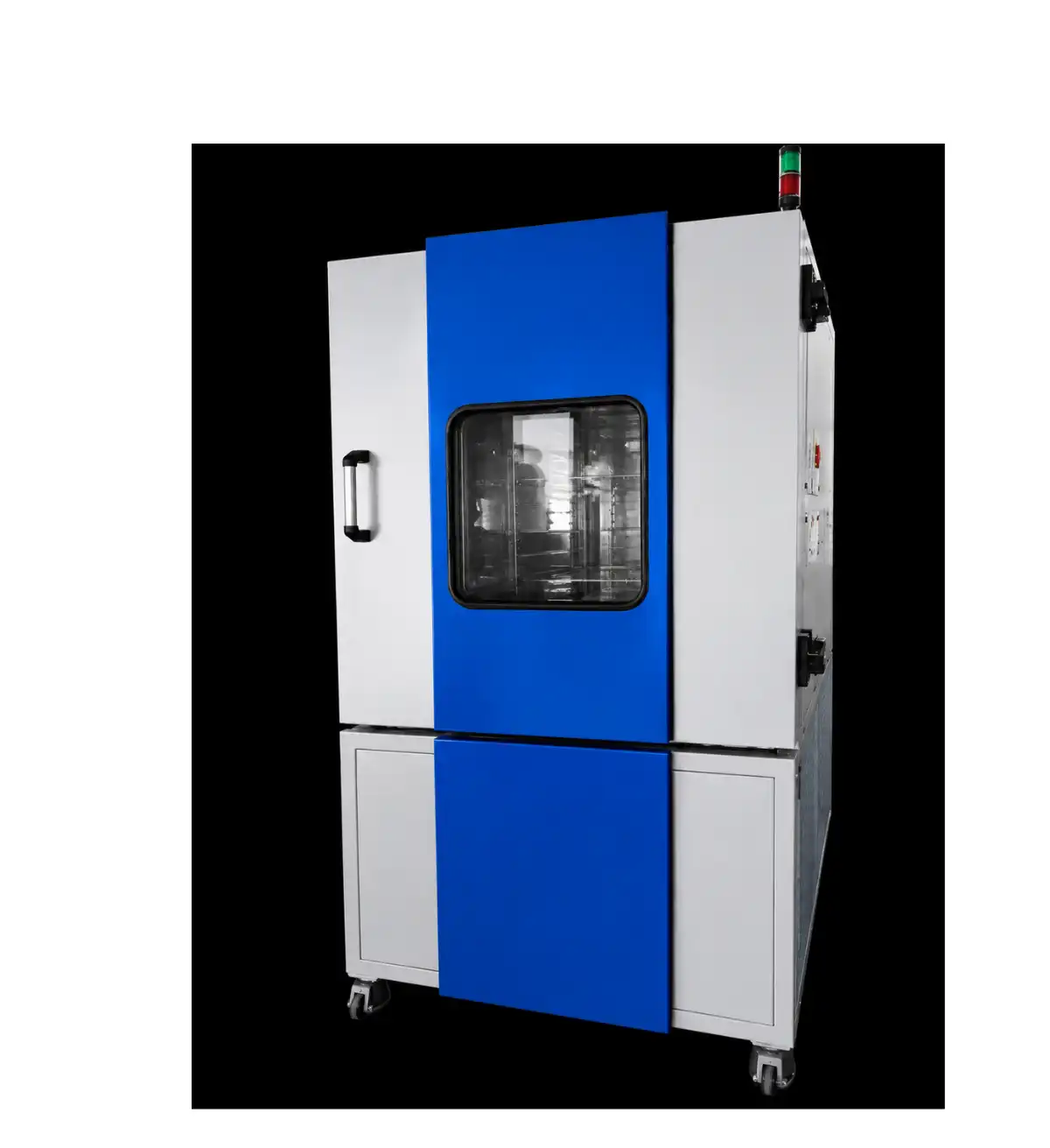
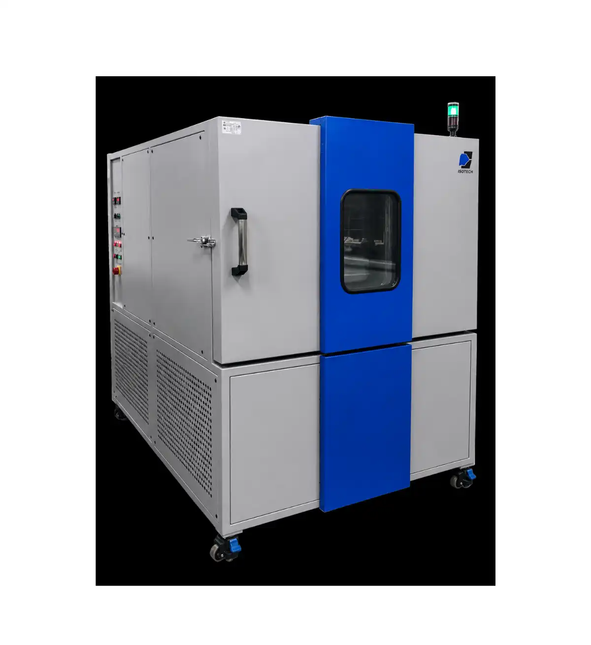
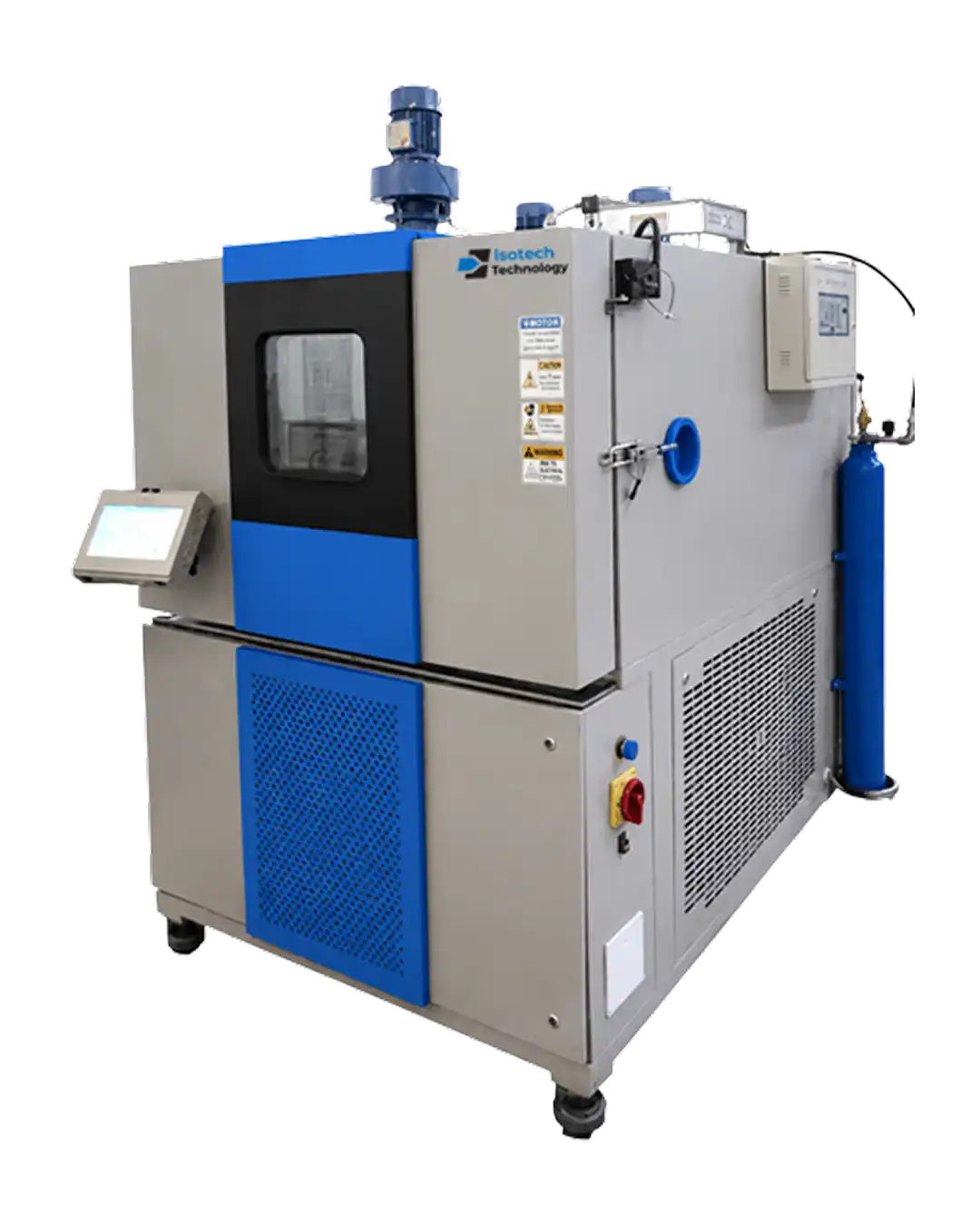
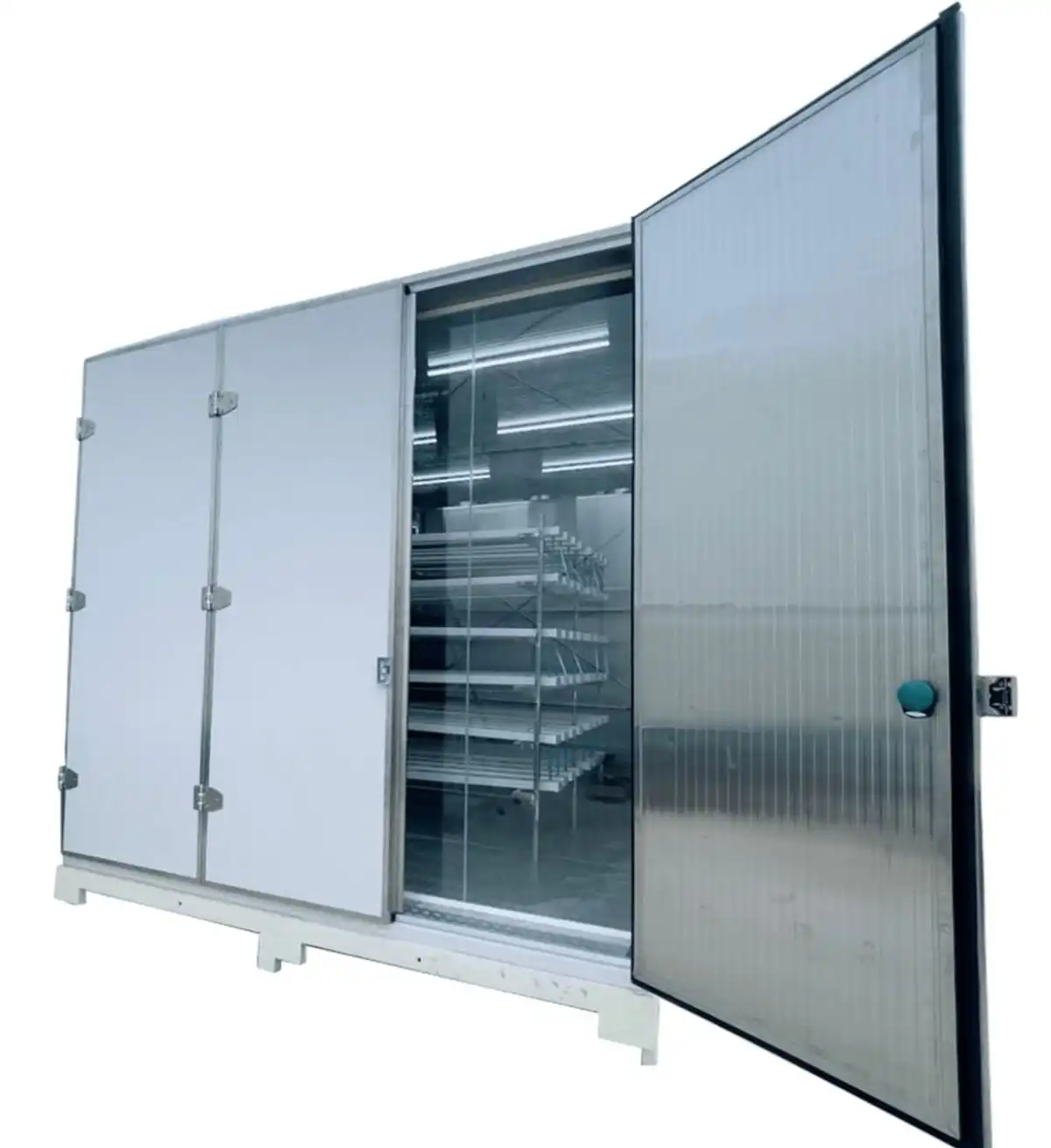
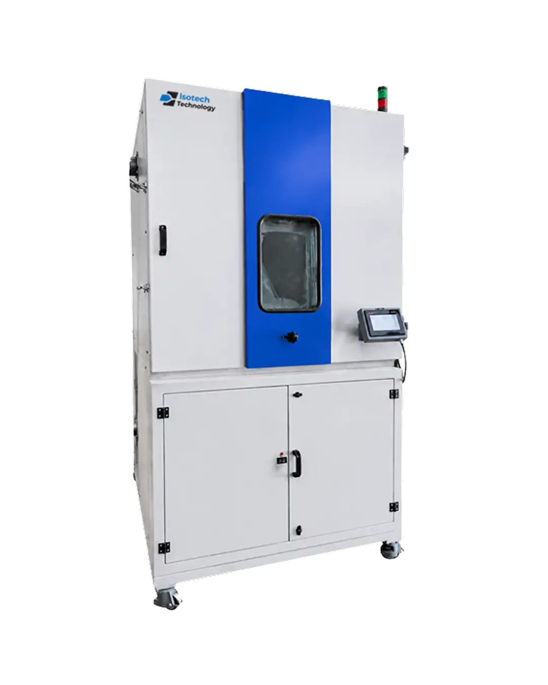
Specify the product, stress profile, load and release objective.
Share the DUT dimensions, quantity, powered load, temperature range, duration, cycling profile, feed-throughs, monitoring, failure criteria and installation utilities.
Burn-In Chamber FAQs.
Practical answers based on ISOTECH’s current Burn-In Chamber material. Final parameters should follow the approved reliability plan and selected equipment configuration.
A controlled environmental chamber that subjects components or systems to sustained or cycled stress so latent defects can be identified before field use.
Burn-in can reveal process, assembly or component defects before release, improving confidence in production quality and reducing the risk of early field failure.
Published examples include capacitors, resistors, integrated circuits, subassemblies, photovoltaic grid inverters, power supplies and complete electronic systems.
ISOTECH publishes two logic-programmable temperature families: ITBIC-60 LO for RT+10°C to +60°C and ITBIC-100 LO for RT+10°C to +100°C, with large configurable volumes.
Selection should address temperature capability and uniformity, usable volume, powered-DUT loading, air distribution, control, monitoring, feed-throughs, safety protection, service access and data requirements.
HALT explores design weaknesses and margins, ALT investigates accelerated wear-out and lifetime confidence, and production burn-in screens individual units for early defects after design qualification.
The published material discusses powered inverter and power-supply testing. Required electrical feeds, heat load, monitoring and protection must be engineered into the final chamber configuration.
Define the product size, quantity, heat dissipation, powered state, maximum temperature, profile, duration, monitoring, access, safety and installation utilities before selecting the model.
The published model table covers a broad volume family. Confirm internal dimensions, racks, cable ports, electrical loading, controls, records and application-specific safety systems with ISOTECH.
Warranty duration and support scope should be confirmed in the commercial proposal for the selected configuration, installation location and service plan.