
Applicable Standards
The Draught Proof Chamber shall be designed and manufactured in compliance with the following standards:
- IS 10322 (Part 1): 2014
- IEC 60598-1 – Annex D / Clause 12.4.1
- IS 16102 (Part 1): 2012 (Reaffirmed 2017)
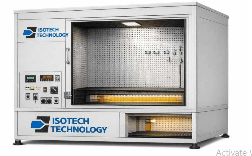
Suitable for temperature rise testing of luminaires, LED lamps, bulbs, and associated lighting accessories
Chamber Construction
| Parameter | Specification |
|---|---|
| Chamber Type | Draught Proof Chamber |
| Construction | Double-walled structure |
| Inner Surface Finish | Black matt finish (low reflectivity) |
| Inner Wall | Perforated sheet construction |
| Outer Body | Powder-coated mild steel |
| Insulation | High temperature thermal insulation |
| Chamber Door | Front access door with sealing arrangement |
| Test Mounting | Provision for mounting luminaires and accessories |
| Air Circulation | Natural convection as per standard |
| Lighting | Internal test observation light (optional) |
Chamber Dimensions
| Parameter | Specification |
|---|---|
| Internal Dimensions | 1700 mm (L) × 900 mm (W) × 900 mm (H) |
| External Dimensions | Approx. 1900 × 1100 × 1200 mm |
| Chamber Volume | Approx. 1.37 m³ |
Temperature Measurement System
| Parameter | Specification |
|---|---|
| Temperature Measurement | Thermocouple based system |
| No. of Channels | 16 Channels Temperature Data Logger |
| Sensor Type | Type-K Thermocouples |
| Thermocouple Quantity | 16 Nos. |
| Measurement Range | 0°C to 300°C |
| Accuracy | ±0.5°C or better |
| Display | Digital multi-channel display |
| Data Logging | PC interface / USB / Software |
| Recording | Real-time temperature recording |
Electrical Control Panel
Integrated control panel mounted with the chamber including:
| Component | Specification |
|---|---|
| Auto Transformer | 10 Amp rating |
| Digital Voltmeter | Panel mounted |
| MCB Protection | Included |
| Power ON/OFF Switch | Provided |
| Indicator Lamps | Power / Heater status |
| Hour Meter | Time totalizer for test duration |
| Terminal Blocks | For thermocouple connections |
| Panel Type | Powder coated control panel |
Optional Ambient Heating System
To simulate higher ambient conditions during testing.
| Parameter | Specification |
|---|---|
| Heating Type | Electric air heaters |
| Heating Chamber | Insulated heater chamber at bottom |
| Temperature Range | Ambient to 50°C |
| Temperature Control | PID Temperature Controller |
| Control Elements | Contactor, MCB protection |
| Heat Selection | Heater selector switches |
| Heating Method | Slow heating with uniform distribution |
Safety Features
- MCB protection for electrical safety
- Over-temperature protection
- Proper earthing arrangement
- Heater safety interlock
- Electrical overload protection
Utilities Required
| Parameter | Requirement |
|---|---|
| Power Supply | 230 V / 1 Phase / 50 Hz |
| Connected Load | Approx. 2 – 3 kW |
| Installation | Indoor laboratory installation |
Scope Of Supply
- Draught Proof Chamber with perforated inner structure
- Black matt internal surface finish
- Control panel with electrical components
- 16 Channel Temperature Data Logger
- 16 Nos. Type-K Thermocouples
- Auto transformer (10 A)
- Digital voltmeter
- Hour meter (time totalizer)
- Electrical protection system
- Optional heating system (if required)
Application
The system is suitable for:
- Temperature rise testing of luminaires
- LED lamps
- LED bulbs
- lighting accessories
- Compliance testing as per IS / IEC lighting standards